|
HeadPlay Video Interference |
|
|
|
A friend brought me his HeadPlay display to look at after replacing its video receiver with a ClearView Receiver and finding that this left him with all kinds of constantly shifting diagonal lines running through the displayed video image which I quickly realized were due to RFI (Radio Frequency Interference). After fixing my friends problem and hearing that many others were having this same issue I created this page with what was done to fix his problem to hopefully help others do the same. |
||
|
|
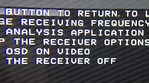
Left - A frame from the video my friend provided to show what the lines looked like. RFI is normally thought of as interference that affects a receivers ability to properly receive a signal of a particular frequency, but in this case the received video from the ClearView receiver is fine and a better term for the RFI would be VFI, or Video Frequency Interference, as the interference is at a much lower frequency than the 5.8 GHZ signal being received and in the same freq. range as the received video signal which is what's actually being affected. (In this case the interfering frequency is ≈ 500KHz. The slope and number of the lines will increase as the freq increases and freq's > ≈ 1 MHz will appear as vertical lines. Likewise, lower freq's will result in less slope and lines until down to 60Hz and only one horizontal line is left.) |
|
|
This problem involves several issues. One is improper grounding. You may have heard the term 'ground loop' and of the importance of having/using a single grounding point, but doing this is easier said than done in many cases, like this case when several separate units powered from the same power source need to be connected. The simplest and easiest way to solve this HeadPlay interference problem is to simply use 2 batteries and power the HeadPlay and ClearView units separately which completely eliminates the grounding issue, but having to use 2 batteries is far from the ideal solution of course. Another issue is the amount of switching regulator noise the HeadPlay unit creates on the battery voltage. I love switching regulators for the fact that they are very efficient, dissipate little heat and save having to deal with all the heat produced by linear regulators, but hate having to deal with the RFI generated by switching regulators which can sometimes be a real pain in the a.., like when it affects GPS receivers. Switching regulator data sheet designs usually include an output filter that reduces RFI to a manageable level, but few deal very much with the RFI that ends up on the supply voltage which often affects other equipment powered from the same source. The HeadPlay PCB and it's LCD Display both have several switching regulators which together create 150mVp-p of noise at ≈ 500KHz on the +12V supply voltage line which is the main problem in this case. (Some have wondered why this problem only affects the ClearView receiver and not the receiver that the HeadPlay comes with and the answer is simply that the HeadPlay receiver is a 5V receiver powered from the fairly well filtered HeadPlay PCB 5V output where as the ClearView receiver is a 12V receiver powered from the HeadPlay 12V line with 150mV of noise which ends up on the receiver video (as well as it's power) ground wiring due to how things must be wired.) Anyway, following is how I corrected the problem. (Clicking on most images will provide a larger image. It may help to also view the 2 schematic images while viewing the first 4 images and reading the associated notes.) |
||
 |
 |
|
|
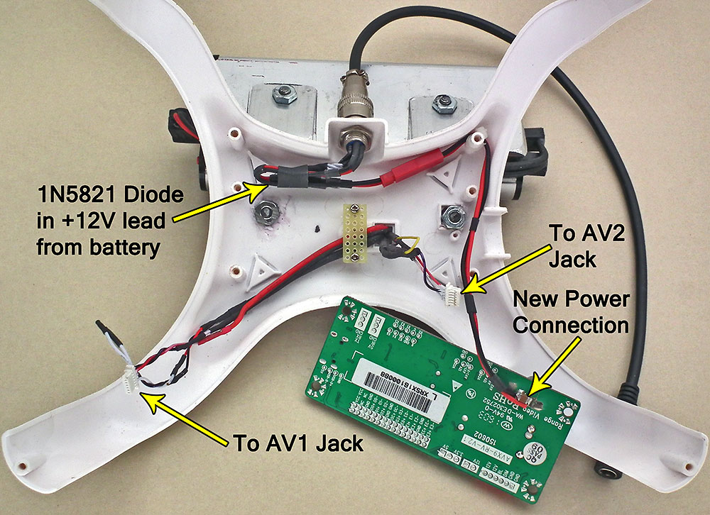
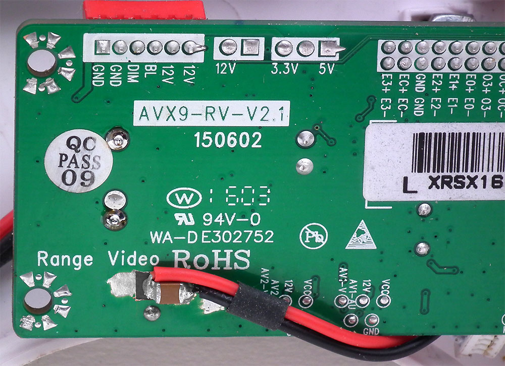
Left image is the wiring after correcting the problem. The HeadPlay connector & cable is only used to supply 12V. Connector wiring, other than +12 and ground, is not used. The 1N5821 diode replaces the 2 removed from the PCB that provided reverse voltage protection. A 2 pin in-line connector in the power leads is provided to allow the PCB to be removed. A small piece of prototype PCB was installed where the original HeadPlay receiver was mounted to keep some of the wiring in place. The Right Image is a closer view of the HeadPlay PCB showing the new power connections and the ceramic capacitor added in parallel with the 470 mfd capacitor located on the top side of the PCB. Some of the PCB ground plain was removed around the + connection to avoid a possible short and some of the solder mask was removed from the PCB ground plain for the ground connection. |
||
 |
 |
|
|
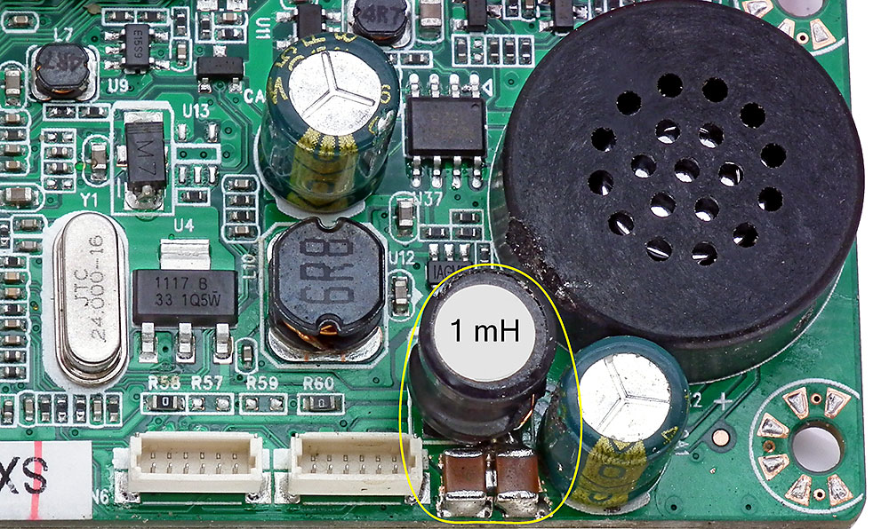
This image shows the inductor and 2 ceramic caps added on the top side of the HeadPlay PCB. The inductor was installed using the pads freed up by removing the 2 protection diodes. Most any inductor from 500 µHy to 1 mHy with as low a DC resistance as you can find will do. (The one shown was < 1 Ω.) The same goes for the value of the ceramic cap's that were used (each was ≈ 30 mfd), but a bit less will also work and, in this case, more is even better. The inductor and all of the cap's used were simply ones salvaged from old PC motherboards and then measured to determine their values. |
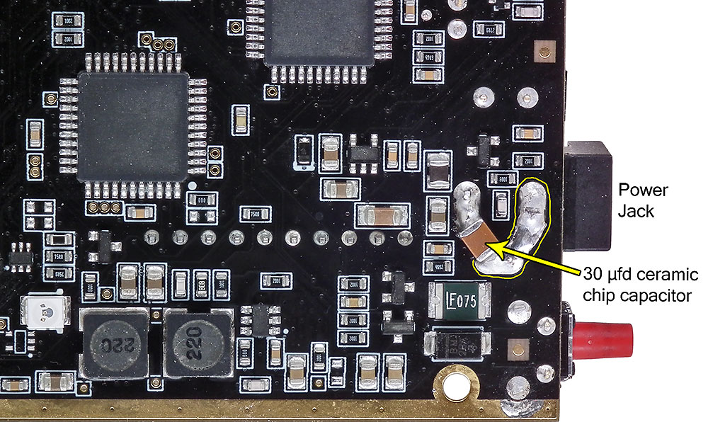
This Image shows a ceramic capacitor that was added across the power jack of the ClearView receiver on the bottom side of the PCB to reduce the RFI from the receivers switching regulators. Again, some of the solder mask was removed from the PCB ground plain and the jack ground connection was tied to the jack's switch connection in order to extend the ground connection to the capacitor. |
|
|
This Image shows the plugs used for the wiring from the receiver AV1 and AV2 output jacks. The plugs were standard straight in-line replacement plugs with plastic threaded on shells that were modified into right angle plugs by cutting the shells shorter and providing a slot for the wiring to exit out the side. After installing the cables the shells were filled with silicon sealant to provide strain relief. Right angled plugs could have simply been used of course, but I didn't have any at the time plus these are shorter and more compact than any of the right angled plugs I have ever seen.
Also shown is a nut that was threaded onto the left SMA antenna connector to keep the receiver PCB from sliding to the right inside the enclosure (due to the enclosure being a bit too long) when an AV plug was inserted as this prevents the plugs from being fully inserted. |
||
|
|
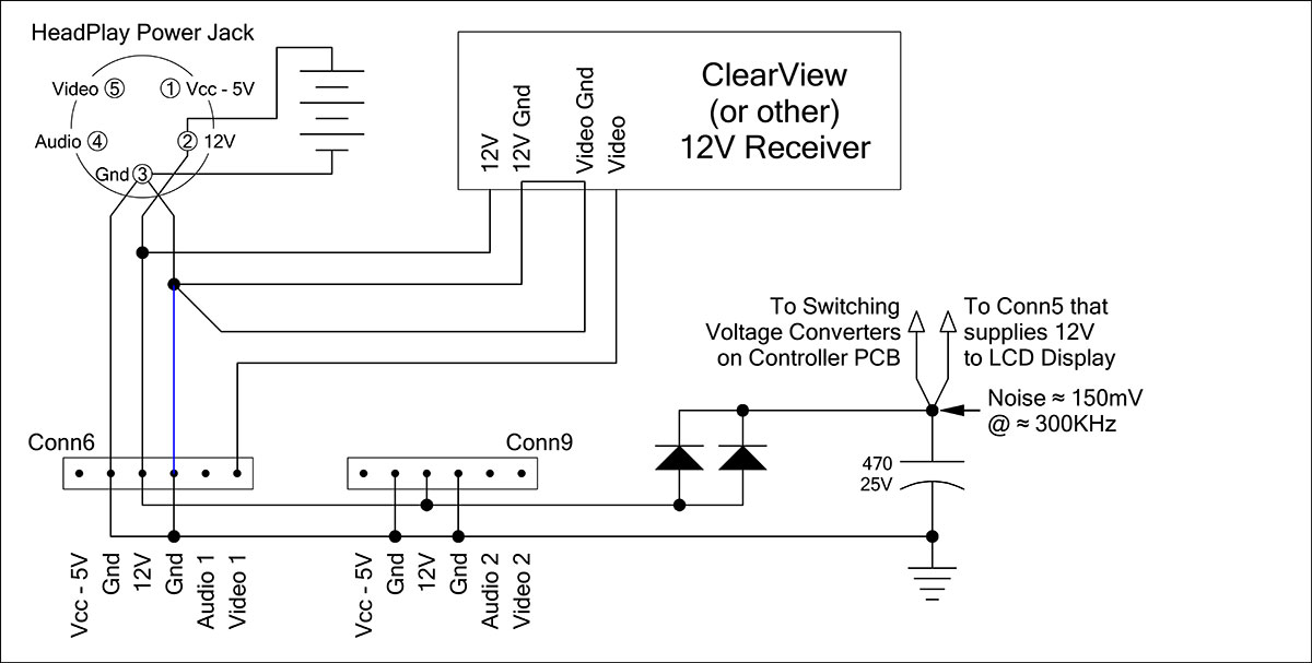
Wiring schematic before correcting the problem. Wired this way, the HeadPlay operating current flows through the ground connection shown in blue and the 150 mV of noise (due to the HeadPlay switching regulators) measured across the 470 mfd capacitor is also present across the Blue ground connection. The Blue ground connection also serves as the Video ground connection which adds the 150 mV of noise to the video signal and creates the video problem. |
|
|
|
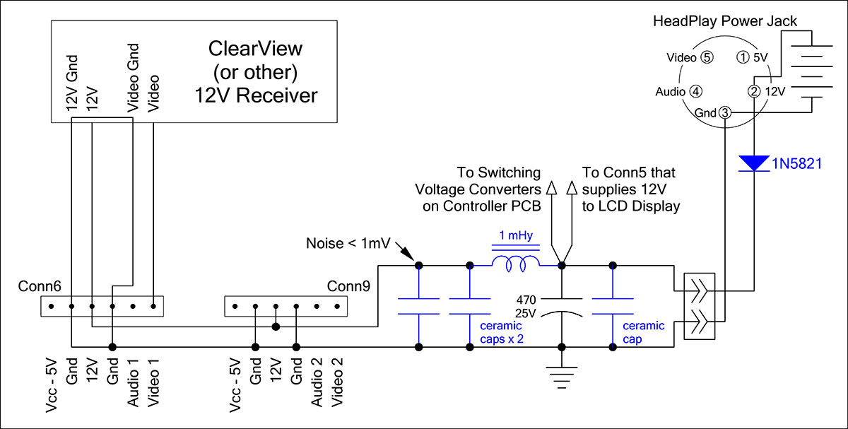
Wiring schematic after correcting the problem. With the ClearView receiver power and video grounds connected in the receiver the only solution is to minimize the HeadPlay switching regulator noise superimposed on the receivers power and video ground wiring. A cap across the 470 mfd cap reduces the HeadPlay regulator noise a bit and allows the inductor and 2 cap's to further reduce the noise on the ClearView receiver supply voltage to <1mV. (The ClearView receiver switching regulators also create a bit of noise voltage on its power and video ground wiring, but not enough to be a problem, especially after an additional cap is added to the receiver as shown earlier.) |
|
|
The schematic doesn't provide any ceramic capacitor values, but they were all ≈ 30 mfd and, like I mentioned before, a bit less will likely work as well and more is even better. Just make sure they are all ceramic SMD type cap's to minimize the ESR. |
||
|
|
Note: If you plan to make your own AV cables (like I did) or use some cables you already have from various other AV equipment, Please Note that ClearView uses one of the less common 3.5mm plug wiring standards for its receiver plugs. | |