1.2 GHz FM Wireless SpyCam
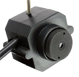 |
After playing with a friends tiny spy cams, I could not resist getting one of my own to experiment with and have available for when a small camera is needed. As usual, it was simply advertised as a 1.2 GHz wireless camera so I did not known that it was FM until after receiving it and glad that it was because it could be compared to the AM ones seen before and hopefully be used with my Comtech FM receivers. The camera uses a CMOS sensor, like the AM camera, which work ok with adequate lighting. The camera is .79" × .79" × 0.6" deep, or slightly more then 1/3 cubic inch, with a 0.2" lens protrusion. |
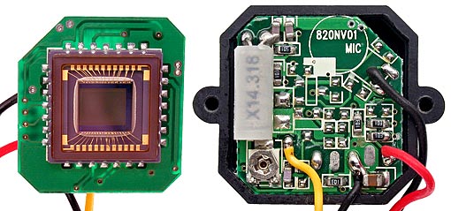
| Left is the CMOS sensor and right is the other side of the camera board shown installed in the camera case. This camera did not include audio, but the circuit board is obviously the same one used for cameras with a mic. The small pot provides video output level adjustment from 0 to 2 volts p-p. The board is .7" x .7" (<1/2 sq. inch.) |
 |
 |
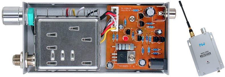
The 3/8" × 1/2" transmitter was sealed in heat shrink tubing to prevent any short-circuits with the camera board when installed in the camera housing. Camera video is applied to a varactor which FM modulates a simple LC oscillator followed by a one transistor amplifier. The camera is labelled as being 200 mW, however this is not the transmitter RF output power, but the power required to operate camera and transmitter at 9 VDC. |
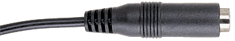 The camera's power cord terminates in a 5mm coaxial jack for connection to a 9 VDC AC power adapter or 9 volt battery using an adapter cable. It was interesting, and a bit confusing, to see 3 conductors coming
from the 2 conductor jack. A black wire from the jack's sleeve was connected to both the transmitter & camera (-9 volt common connection), a white wire from the jack's center pin connected to the transmitter (+9 volts) and a red wire connected to the camera, but it showed no continuity to either
the black or white wire. However, powering the camera showed that the red wire provided +5 volts to the camera which meant a 5 volt regulator was embedded in the coaxial jack housing and that this was strictly a 5 volt camera unlike the AM spy cameras that were fed 9 volts, although a 5 volt regulator
may have been on the AM camera boards. The camera's power cord terminates in a 5mm coaxial jack for connection to a 9 VDC AC power adapter or 9 volt battery using an adapter cable. It was interesting, and a bit confusing, to see 3 conductors coming
from the 2 conductor jack. A black wire from the jack's sleeve was connected to both the transmitter & camera (-9 volt common connection), a white wire from the jack's center pin connected to the transmitter (+9 volts) and a red wire connected to the camera, but it showed no continuity to either
the black or white wire. However, powering the camera showed that the red wire provided +5 volts to the camera which meant a 5 volt regulator was embedded in the coaxial jack housing and that this was strictly a 5 volt camera unlike the AM spy cameras that were fed 9 volts, although a 5 volt regulator
may have been on the AM camera boards. |
|
 |
|
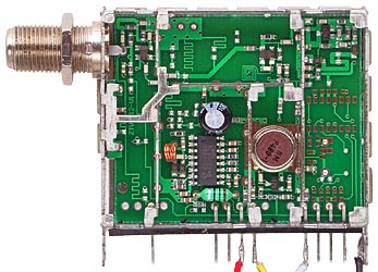
| The FM receiver looks similar to the AM spy camera receivers except for the video output driver that is also on the 5 volt regulator circuit board. And similar to the AM receivers, the 5 volt regulator came with a series voltage dropping resistor that I will be replacing with a diode to add reverse polarity protection. | |
| The receiver is tuned using the front panel pot which supplies a variable voltage to a voltage controlled local oscillator, but the unpopulated lower-right circuit board area is laid out for a PLL VCO control circuit which is obviously an available option. PLL control would be a big improvement
and all my AM spy camera transmitter and receiver comments regarding tuning stability also apply to this FM transmitter and receiver. A mixer receives input from the local osc and a single stage RF amp and a comb filter provides a 480 MHz I.F. input to a Zarlink SL1461 PLL FM Demodulator. The SL1461 provides an AGC voltage which is available on one of the tuner pins. |
 |
| When time permits I plan to measure this tuners sensitivity, compare it to the Comtech receiver and provide any other information I come up with. It is too bad that those selling items like this do not provide more information about them when ordering so one could know if an AM or FM unit would be received. It would also be nice to find where a PLL controlled VCO version of this receiver could be ordered. | |
Also see 1.2 GHz AM Wireless SpyCam