Homebrew Directional Coupler
|
|
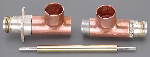 |
The coupler is to be panel mounted so a chassis mount "N" connector for RG-8 type cable was used for one connector and a regular crimp style was used for the other.
A lathe was used to machine and shorten both connectors in addition to turning the center conductor from 1/4" brass rod. |
|
Two new, bright, shiny pennies, if sized to the correct diameter, looked perfect to use for the copper discs required to construct the sensing elements. However, while drilling the center hole in the pennies I discovered that they were not solid copper, but copper plated steel. Solid copper discs would likely be easier to solder, so I raided the penny jug and used a magnet to select two non-magnetic pennies.
Drilling quickly showed that these were also not solid copper, but simply a copper plated non-magnetic metal. So another trip was made to the penny jug after doing some research on penny composition. |
||
 |
The pennies were mounted on a 4-40 bolt using the 1/8" center hole and sized, using a lathe, for a press-fit into the element bodies. Two more 1/8" holes were drilled in each disc, for an insulated support post and brass tubing sleeve, before each disc was pressed and silver soldered into a 1/2" copper sleeve.
|
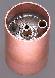 |
 Then the support post and brass sleeve were pressed into place and silver soldered by reheating the assembly. The feed-thru capacitor was then installed in the center hole and soldered with regular 60/40 or 63/37 solder which
has a lower melting temperature than silver solder and is used for any further soldering to prevent disrupting previous work.
Then the support post and brass sleeve were pressed into place and silver soldered by reheating the assembly. The feed-thru capacitor was then installed in the center hole and soldered with regular 60/40 or 63/37 solder which
has a lower melting temperature than silver solder and is used for any further soldering to prevent disrupting previous work.
 |
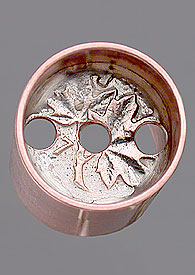
Bottom View of a completed element.
The loop termination resistor can be seen installed inside the brass sleeve on the right side. A piece of 1/16" diameter brass tubing has been placed over the portion of the resistor lead running horizontal and soldered to the support post on the left. The extra solder seen on the 1/16" brass tubing has been added to adjust the loop's cross sectional area and match the sensing loop to the termination resistor impedance. The small black SMT 1N5711 diode can be seen soldered between the support post and the feed thru capacitor in the center hole. |
 |
Inside Upper Section A 1K resistor is connected from the lower sections feed thru capacitor to several capacitors for additional RF filtering and then to the top output feed-thru capacitor.
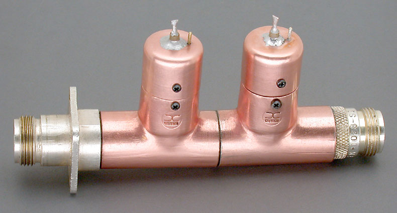
A Completed Coupler Element |
 |
 |
|
| A few of the many element variations built and tested during my long and frustrating attempt to homebrew a directional coupler element. Construction articles make it sound easy. None of my elements had a problem indicating forward power, but I couldn't seem to be able to properly balance the loop to only sense reverse power. I know nothing is perfect in the real world, but I felt that the amount of forward power affecting my reflected power readings was excessive. I tried everything that I could think of to improve the situation. When just about ready to give up I finally took the time to actually calculate the element's directivity which was 30 dB which is considered "excellent". Rather than having a problem, I was simply trying to achieve unrealistic performance. |  |
|
|
| Date |
Composition |
| 1908 to 1920 |
95.5% copper, 3.0% tin, 1.5% zinc |
| 1920 to 1941 |
95.5% copper, 3.0% tin, 1.5% zinc |
| 1942 to 1977 |
98.0% copper, 0.5% tin, 1.5% zinc |
| 1978 to 1979 |
98.0% copper, 1.75% tin, .25% zinc |
| 1980 to 1981 |
98.0% copper, 1.75% tin, .25% zinc |
| 1982 to 1996 |
98.0% copper, 1.75% tin, .25% zinc |
| 1997 to 1999 |
98.4% zinc, 1.6% copper plating |
| 2000 to date |
94.0% steel, 1.5% nickel, 4.5% copper plating |
|
U.S. Pennies |
|
| Date |
Composition |
| 1793 to 1837 |
Pure copper |
| 1837 to 1857 |
Bronze (95% copper, 5% tin and zinc) |
| 1857 to 1963 |
88% copper, 12% nickel (coins have a whitish appearance). |
| 1864 to 1962 |
Bronze (95% copper, 5% tin and zinc) |
| 1962 to 1982 |
95% copper, 5% zinc (bronze with tin removed) |
| 1982 |
97.5% zinc, 2.5% copper plating |