2.4 GHz FM Wireless Color Camera
|
My friend, Jeff, gave me his small wireless camera to see if it's operating range could be improved by perhaps a better receiver antenna as he would like to try using the camera on a small R/C airplane. This was the first wireless camera and receiver seen with cases that were not screwed, but glued, together which made opening them a bit difficult. But luckily, little glue had been used and they were eventually opened by gently prying and working slowly. |
|
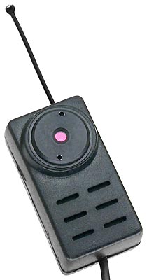 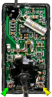 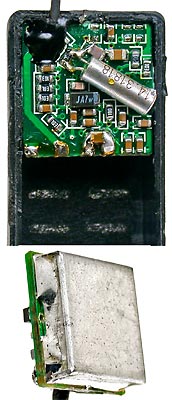 |
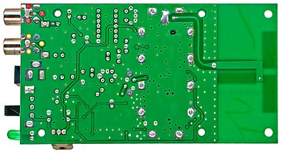
The camera case is made to accommodate a mic, but this camera version does not have one and transmits video only. The camera operates on 5VDC and supplies video to a sealed transmitter module in the lower half of the case. The modules RF output is applied to a trace on the camera board which connects to the antenna at the top of the case. Green arrow is deviation adjustment & Yellow arrow is frequency adjustment. |
|
Like my 1.2 GHz FM Wireless SpyCam, this camera's power cord terminates in a 5mm coaxial jack with a 5 volt regulator embedded in the coaxial jack housing. Spec's found on a web page indicates input voltage is 5−12 volts @ 100ma, however the voltage regulator requires >5.45 volts to provide a regulated 5 volts
and the actual current drain was measured to be 72ma. The low regulator dropout voltage was nice to see. |
|
  |
|
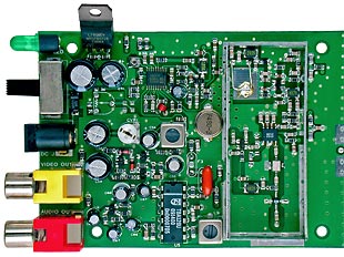 |
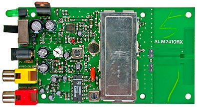
Receiver Board - Top and Bottom Sides The receiver is Model SW-P-MC for 2451 MHz and the input voltage is spec'd as 12VDC, but it operates on 8 volts from a regulator that requires >9.9 volts to provide a regulated 8 volts. For battery operation it would be nice to have a regulator with a lower dropout voltage then 1.9 volts, but it would not be hard to replace the existing L7808 with a lower dropout voltage type. The L7808 will accept up to 30 volts, however the regulator would likely over heat with more then about 12−18 volts. The actual current drain was measured to be 170ma. The receiver has both video and audio outputs, but the version of camera with this unit only transmits video. |
| This receiver is different from other non PLL receivers I have seen in that it has an AFC circuit, rather then a manual fine tuning control, for frequency adjustment as the receiver and/or transmitter drifts. There were more video dropouts then expected when the transmitter was moved about so the transmit frequency was checked and found to be very close to 2451 MHz. But after determining the exact frequency the receiver expected and adjusting the transmitter frequency slightly to match, the dropouts seem to have disappeared. | |
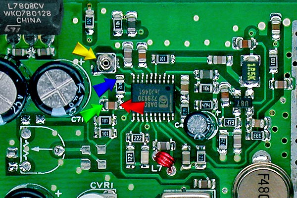 |
This receiver uses a Yellow arrow points to the AGC threshold adjustment. Red, Blue & Green arrows point to connection points used for my "S" meter cct. Red is +5V, Blue is AGC & Green is Ground. See Swan Rx.pdf for a schematic of my "S" meter, U87 & TDA8012 sections of the receiver. |
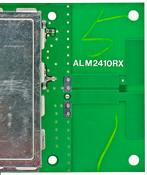 |
The receiver's antenna is a 1/2 wave dipole extending from the ground plane on the top side of the receiver circuit board. Place your cursor over the image to see the antenna's coupling section and transmission line to the receiver input which is on the bottom side of the board.
|